New integrable areal confocal head
![]()
The S mart 2 is the only autonomous areal confocal profilometer in the market. Its powerful features and the compact design turns it into a breakthrough in the optical field.

The S mart 2 areal confocal capability images an area at a time, so the lateral resolution and X and Y remain the same, unlike point or line confocal chromatics.


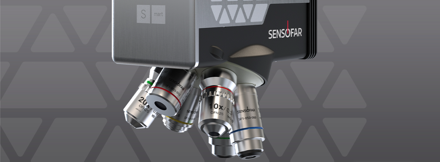
To scan with the most suitable technology, the S mart 2 comes with three technologies to measure in the same head: Ai Focus Variation,
Confocal , and Interferometry.


Just focus on the surface and S mart sensor will do the rest. Our sensors product portfolio has been designed to fulfill the automatization typically required in manufacturing lines.

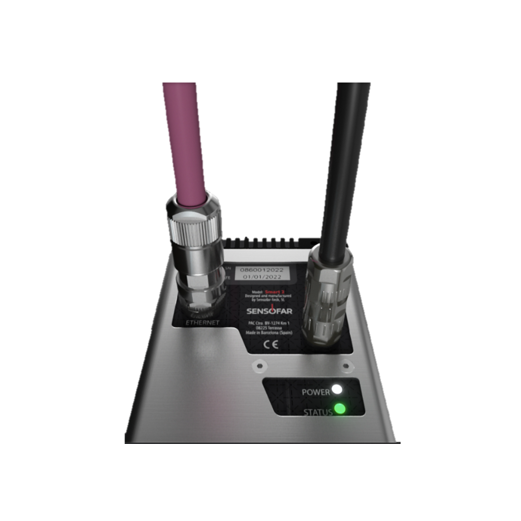
The measurement is done with just one click, the sensor finds the focus, optimizes the light and Z range and the user gets the result.

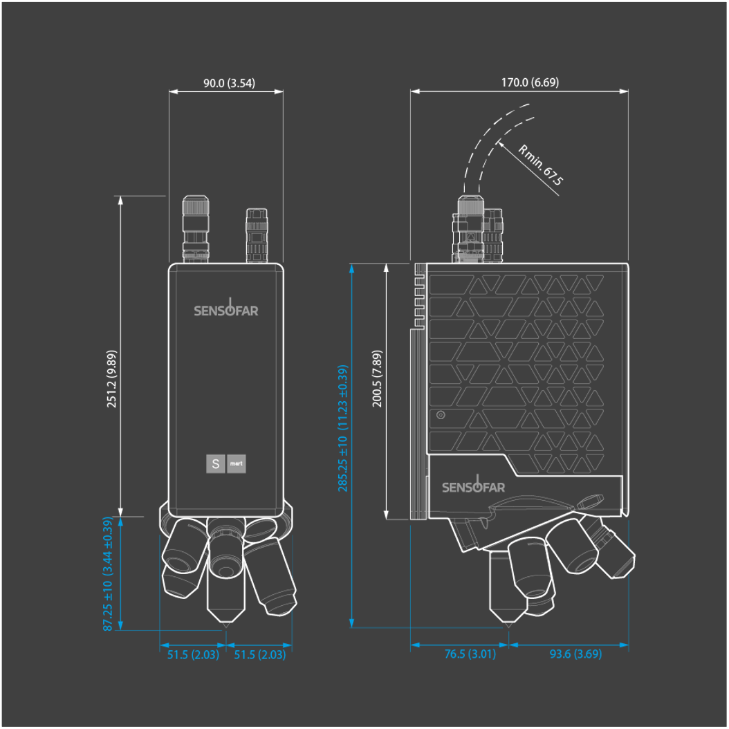
mm (inches)
Weight: 5.3 Kg (11.7 lbs)

Confocal Interferometry Ai Focus Variation
CSI


580 nm 460 nm
| MAG | 5X | 10X | 20X | 50X | 100X |
| NA | 0.15 | 0.30 | 0.45 | 0.80 | 0.90 |
| WD (mm) | 20 | 15.8 | 3.0 | 1.0 | 2.00 |
| FOV1 (µm) | 2820 x 2820 | 1410 x 1410 | 700 x 700 | 280 x 280 | 141 x 141 |
| Spatial sampling2 (µm) | 2.76 | 1.38 | 0.69 | 0.27 | 0.07 |
| Optical resolution3 (µm) | 1.11 | 0.55 | 0.37 | 0.21 | 0.15 |
| Measurement noise4 (nm) | 120 | 45 | 10 | 4 | 3 |
| Maximum slope5 (º) | 9 | 17 | 27 | 53 | 64 |
1 Maximum field of view with 2/3” camera and 0.25X optics. 2 Pixel size on the surface. 3 L&S: Line and Space, half of the diffraction limit according to the Rayleigh criterion. Values for blue LED in brightfield objectives. 4 Measurement noise is measured as the difference between two consecutive measurements of a calibration mirror placed perpendicular to the optical axis. Values obtained in a VC-E vibration environment. 5 On smooth surfaces. Up to 86° on rough surfaces. Other objectives are available.
| MAG | 2.5X | 5X | 10X | 20X | 50X | 100X |
| NA | 0.075 | 0.13 | 0.30 | 0.40 | 0.55 | 0.70 |
| WD (mm) | 10.3 | 9.3 | 7.4 | 4.7 | 3.4 | 2.0 |
| FOV1 (µm) | 5650 x 5650 | 2820 x 2820 | 1410 x 1410 | 700 x 700 | 280 x 280 | 140 x 140 |
| Spatial sampling2 (µm) | 5.52 | 2.76 | 1.38 | 0.69 | 0.27 | 0.07 |
| Optical resolution3 (µm) | 2.32 | 1.34 | 0.58 | 0.44 | 0.32 | 0.25 |
| System noise4 (nm) | < 5 | |||||
| Maximum slope5 (º) | 4 | 7 | 17 | 24 | 33 | 44 |
1 Maximum field of view with 2/3” camera and 0.25X optics. 2 Pixel size on the surface. 3 L&S: Line and Space, half of the diffraction limit according to the Rayleigh criterion. Spatial sampling could limit the optical resolution for interferometric objectives. Values for white LED in interferometric objectives. 4 Measurement noise is measured as the difference between two consecutive measurements of a calibration mirror placed perpendicular to the optical axis. Values obtained in a VC-E vibration environment. 5 On smooth surfaces.
| Z | LINEAR STAGE |
| Vertical range | 20 mm (0.79″) |
| Resolution | 5 nm |
| STANDARD | VALUE | LINEAR SCANNER1 | TECHNIQUE |
| Step Height (H) | <10 | U= (0.005 + H/50) μm σ < 10 nm |
Confocal, AiFV & CSI |
| >10 | U = (0.120 + H/120) μm σ < 10 nm |
Confocal, AiFV & CSI |
1 Values obtained in a VC-E vibration environment. Objective used for Confocal and Ai Focus Variation 50X 0.80 NA and for CSI 50X 0.55NA. Resolution 1220×1024 pixels. Uncertainty (U) according to ISO/IEC guide 98-3:2008 GUM:1995, K=1,96 (level of confidence 95%). σ according to 25 measures. For steps smaller than 5 μm, σ < 5 nm.


